The "hello world" of microcontroller programming is making an LED blink. One of the initial steps in learning how to program a new microcontroller is to accomplish this. A great tool for monitoring activity at the output pins is an LED. When the LED turns on, you can see that the pin to which it is linked is high. The programming techniques used to operate an LED are the same programming concepts used to control a large number of other modules, including motors, relays, buzzers, and other sensors.This tutorial will teach you how to control several LEDs simultaneously, change the speed at which an LED blinks, and make them turn on and off. The pinMode(), digitalWrite(), and delay() functions will also be covered.
WHAT LEDs DO
Electrical current can only flow in one way through diodes. They function similarly to an electrical one-way valve. The diode's schematic symbol is as follows:
Diodes and LED both only allow current to travel in one way. But as current passes through LEDs, they also produce light. Light-emitting diode is what it stands for. The LED schematic looks like this:
POLARITY OF LEDS
LEDs have polarity because current can only travel in one way. They must therefore be connected in the proper direction in order for them to function. The anode is the portion of the LED that is connected to a positive voltage. The cathode is the side that is connected to ground:
The anode is the longer wire, and the cathode is the shorter wire. The cathode side of the LED may have a flat side made of plastic.
LED BRILLIANCE
How much current is permitted to pass through an LED affects how brilliant it is. The LED can be made brighter or darker by varying the current. However, the amount of electricity that can pass through an LED is limited. If you give them too much current, they will shortly burn out. We connect a current-limiting resistor in series with the LED and the power source to restrict the flow of current:
HOW TO ATTACH A LIGHT TO AN ARDUINO
The components required to connect an LED to the Arduino are as follows:
- Arduino Uno
- One LED
- One 200-1K Ohm resistor
- Breadboard
- Jumper wires
To connect the LED and current-limiting resistor to the Arduino, adhere to the wiring diagram below:
The current limiting resistor's value can range from roughly 200 Ohms to roughly 1K Ohms.
HOW TO USE ARDUINO TO PROGRAM AN LED
Upload the following code to the Arduino once you've connected the LED and current-limiting resistor. In this drawing, the LED will flash on for one second, then off for another, and so on.
void setup() {
pinMode(13, OUTPUT);
}
void loop() {
digitalWrite(13, HIGH);
delay(1000);
digitalWrite(13, LOW);
delay(1000);
}
A DESCRIPTION OF THE CODE
The Arduino must first be informed of the pin that the LED is attached to and set as an output. The setup() section's pinMode() method is used for it. The pin number and the input/output mode are the two arguments to the pinMode() function:
pinMode(pin, mode);
Pin 13 is connected to the LED, making it an output pin, thus we use:
In a loop, the code in the loop() section will be run again. We must apply electric current to the LED in order for it to turn on. To change a digital pin's voltage state, use the digitalWrite() method. The pin number and the voltage state (high or low) are its two arguments:
digitalWrite(pin, value);
A high voltage level for the Arduino is 5 volts, and a low voltage level is 0 volts. We write a high voltage to pin 13 as follows to turn on the LED:
The Arduino must then be instructed as to how long pin 13 should be high. With the delay() function, we accomplish that. The Arduino is instructed to pause and wait by the delay() function before continuing with the next line of code. The delay time in milliseconds is indicated by the number enclosed in parentheses:
We delay for 1,000 milliseconds so that the LED will blink once every second:
We must switch off the LED now that it has been on for one second. In order to send a low signal to pin 13, we once more use the digitalWrite() function.
We then wait an additional 1000 milliseconds:
By adjusting the numbers in the two delay() calls, you may modify how long the LED remains on or off.
HOW TO LINK TWO LEDS TO AN ARDUINO
The following components are required to connect two LEDs to the Arduino:
- Arduino Uno
- Two LEDs
- Two 200-1K Ohm resistors
- Breadboard
- Jumper wires
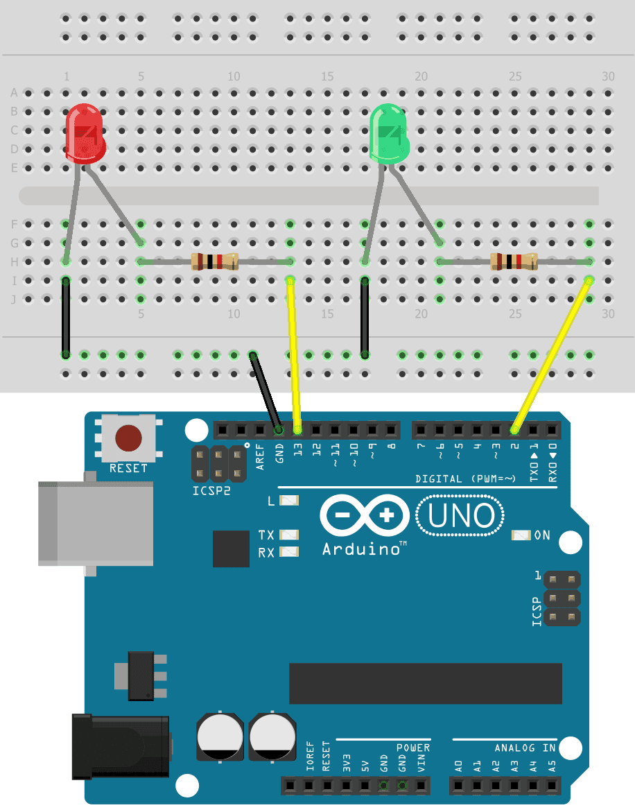
Let's add another LED to this circuit now that we've learned how to attach one to the Arduino. We can supplement the red LED with a green LED. Here's how to wire the circuit together:
The current limiting resistors can have resistance values ranging from 200 Ohms to 1K Ohms.
HOW TO USE THE ARDUINO TO PROGRAM TWO LEDS
To program the two LEDs, we simply repeat the code for a single LED:
int redLED = 13;
int greenLED = 2;
void setup() {
pinMode(redLED, OUTPUT);
pinMode(greenLED, OUTPUT);
}
void loop() {
digitalWrite(redLED, HIGH);
delay(1000);
digitalWrite(redLED, LOW);
delay(1000);
digitalWrite(greenLED, HIGH);
delay(1000);
digitalWrite(greenLED, LOW);
delay(1000);
}
The only difference here is that pin 13 is put in the redLED variable and pin 2 is kept in the greenLED variable. Instead of the pin number, these variables are utilized in the pinMode() and digitalWrite() routines.
After connecting the LEDs and running the above program, you should notice the two LEDs blinking on and off:


1 Comments
If you have any queries, please tell them in the comments section!
ReplyDelete