
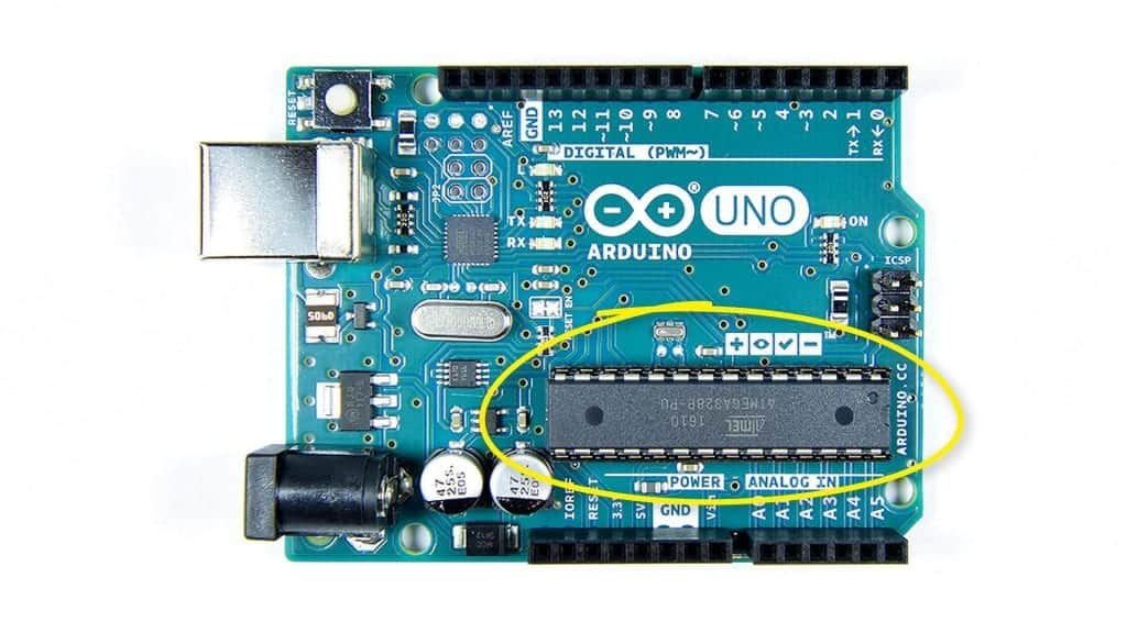
MICROCONTROLLER ATMEGA328
The ATMEGA328 microcontroller is at the heart of the Arduino. The ATMEGA328 was designed for industrial automation systems and requires sophisticated electrical engineering and programming abilities to deal with directly. The Arduino was created to simplify programming and attaching devices to the ATMEGA328 microcontroller.
The ATMEGA328 microprocessor is connected to the PCB via a female pin socket and can be removed:
PIN GPIO
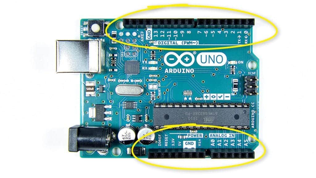
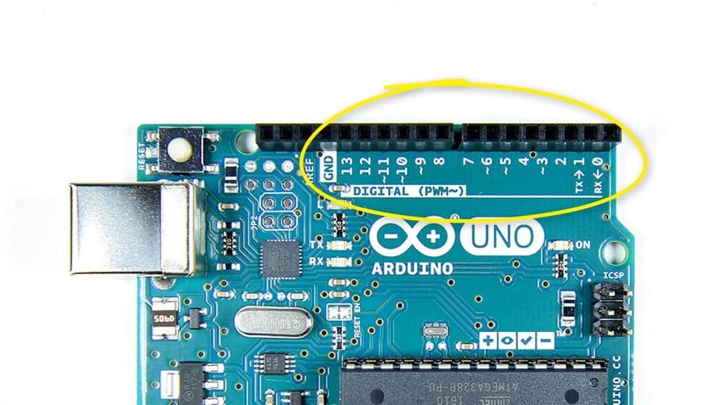
DIGITAL PINS
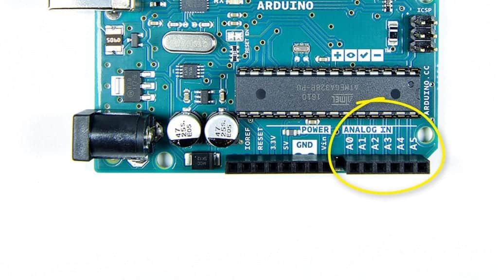
PINS ANALOG
Any voltage between 0V and 5V can be generated or detected via the analog pins. They are numbered from A0 through A5:
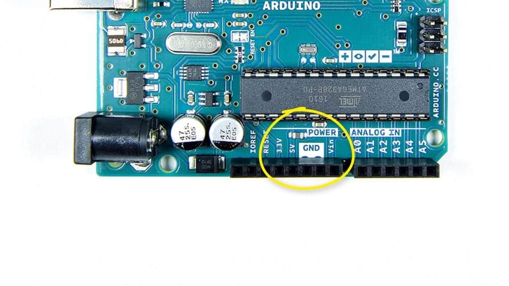
PINS FOR POWER AND GROUND
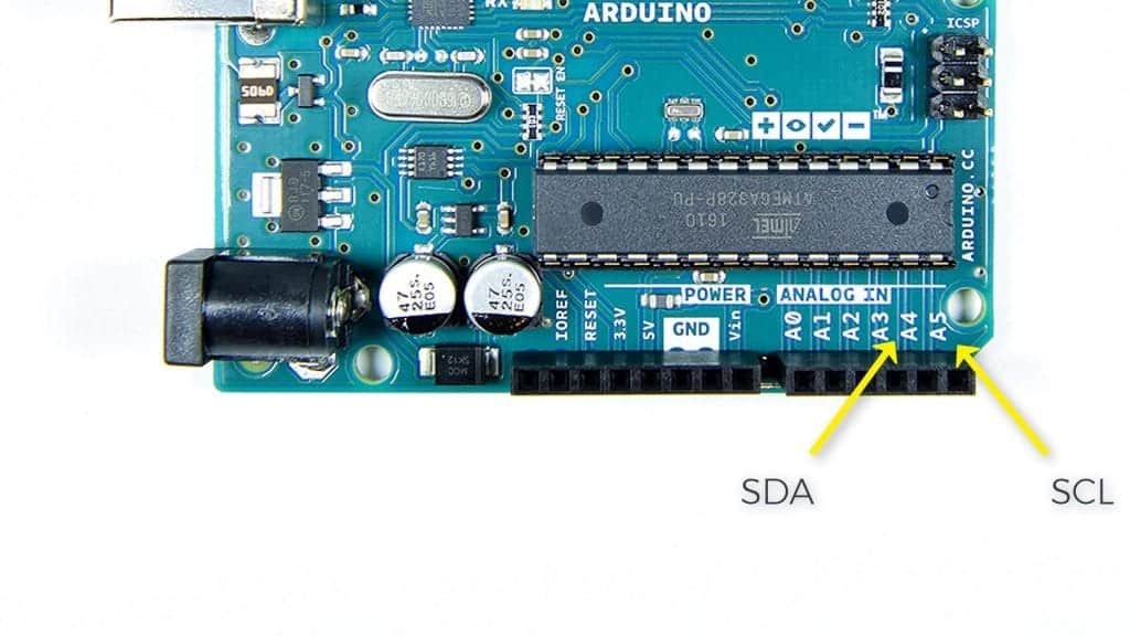
PINS FOR SDA AND SCL
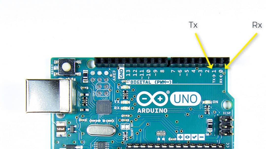
PINS FOR TX AND RX
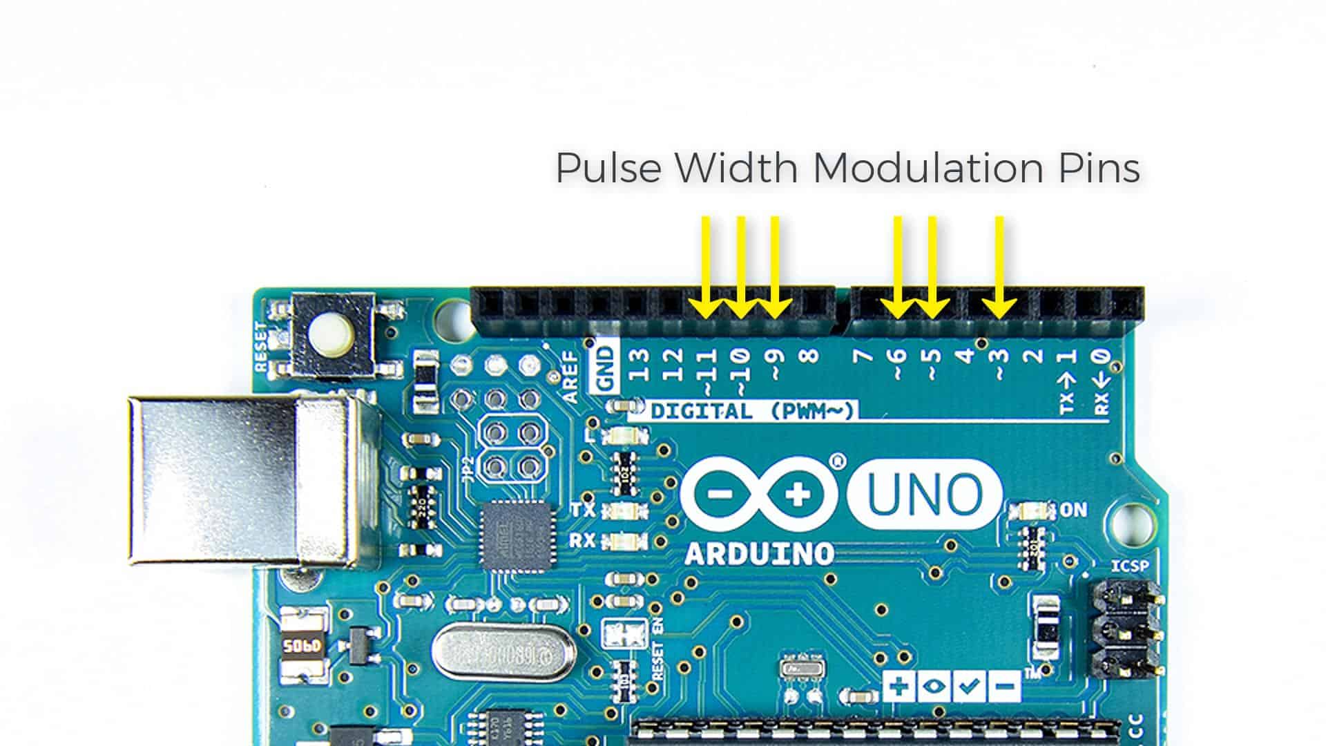
PINS FOR MODULATING PULSE WIDTH
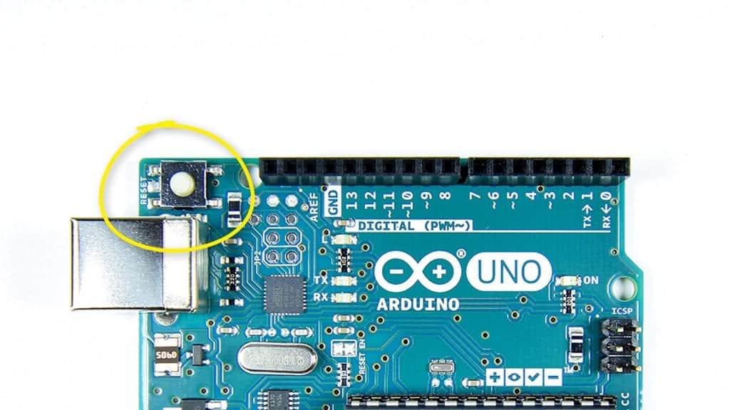
BUTTON RESET
The reset button restarts the Arduino and causes the sketch to begin again:
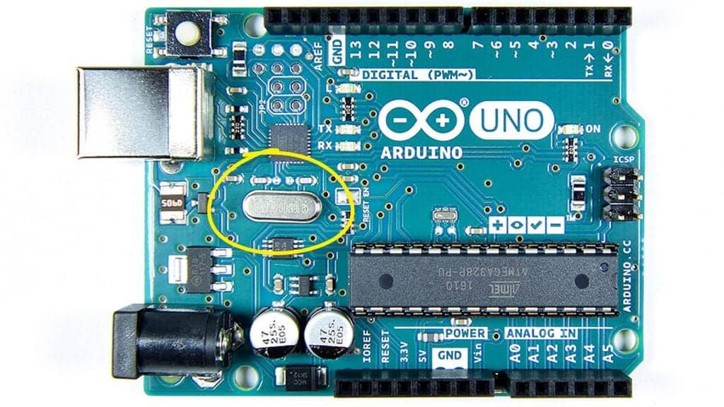
OSCILLATOR OF CRYSTAL
The crystal oscillator allows the Arduino to retain time as well as create pulse width modulation and serial communication signals. Because the crystal oscillator is 16 Mhz, the Arduino can execute binary instructions at 16 Mhz or 16 million times per second:
POWER SOURCE
The power supply is located on the Arduino's PCB on the lower left side:
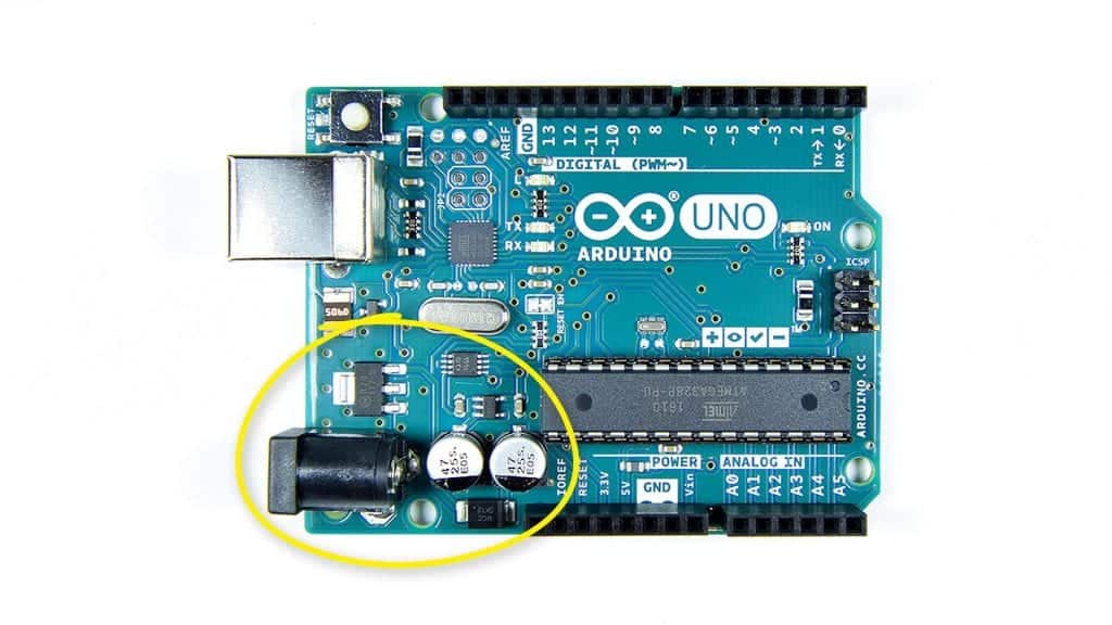
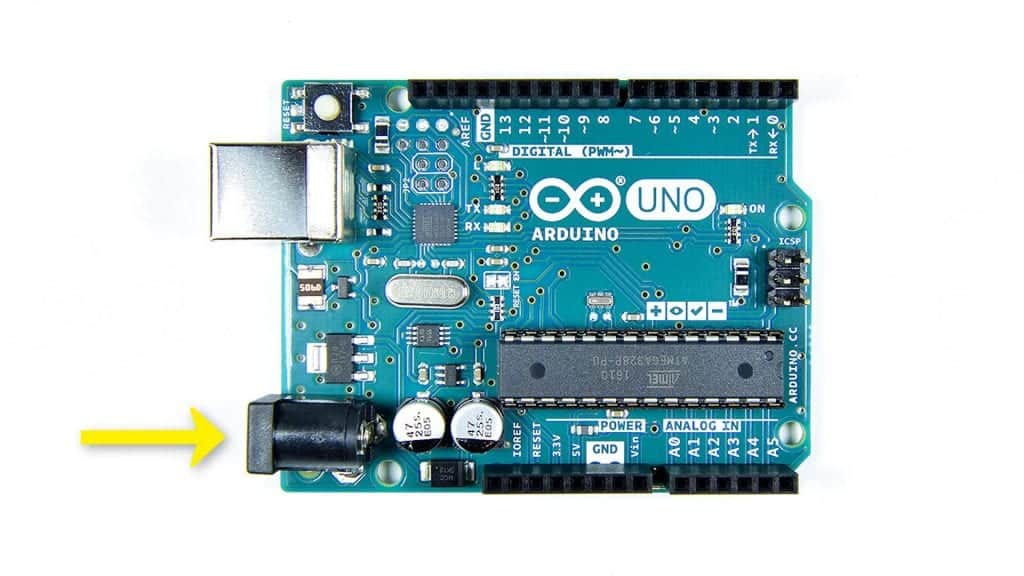
JACK FOR POWER INPUT
The Arduino can be powered using the USB cable's 5V supply. However, if you want to use the Arduino without a computer, you can use a 7 to 12V AC to DC power supply adapter. The power adapter is linked to the Arduino through the power input jack:
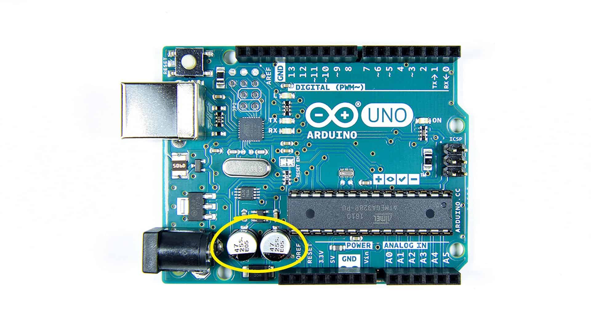
CAPACITORS FOR DECOUPLING POWER SUPPLY
The power supply decoupling capacitors filter the incoming power supply to prevent voltage spikes from damaging the board:
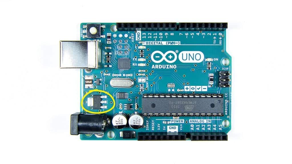
REGULATOR OF VOLTAGE
The voltage regulator reduces the 7 to 12-volt input power to 5 volts, which is the Arduino's working voltage:
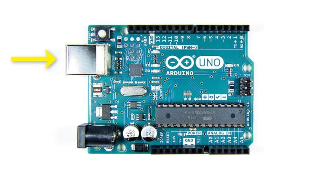
USB PORT CONNECTOR
Using USB connectivity, programs are uploaded from your computer to the Arduino. When serial data is displayed on the serial monitor, it is also transmitted over a USB to your computer. While linked to your computer, the USB cord can also power the Arduino. The USB cable connector is as follows:
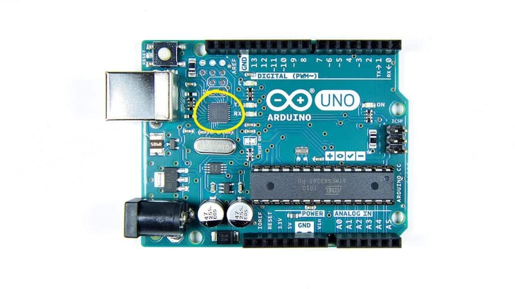
CHIP FOR USB CONTROL
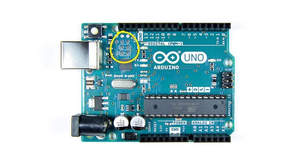
PINS FOR USB CONTROL CHIP PROGRAMMING
PINS FOR ATMEGA328 PROGRAMMING

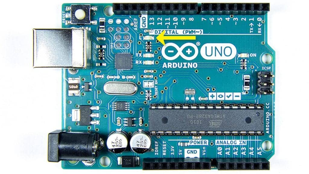
LED PIN 13
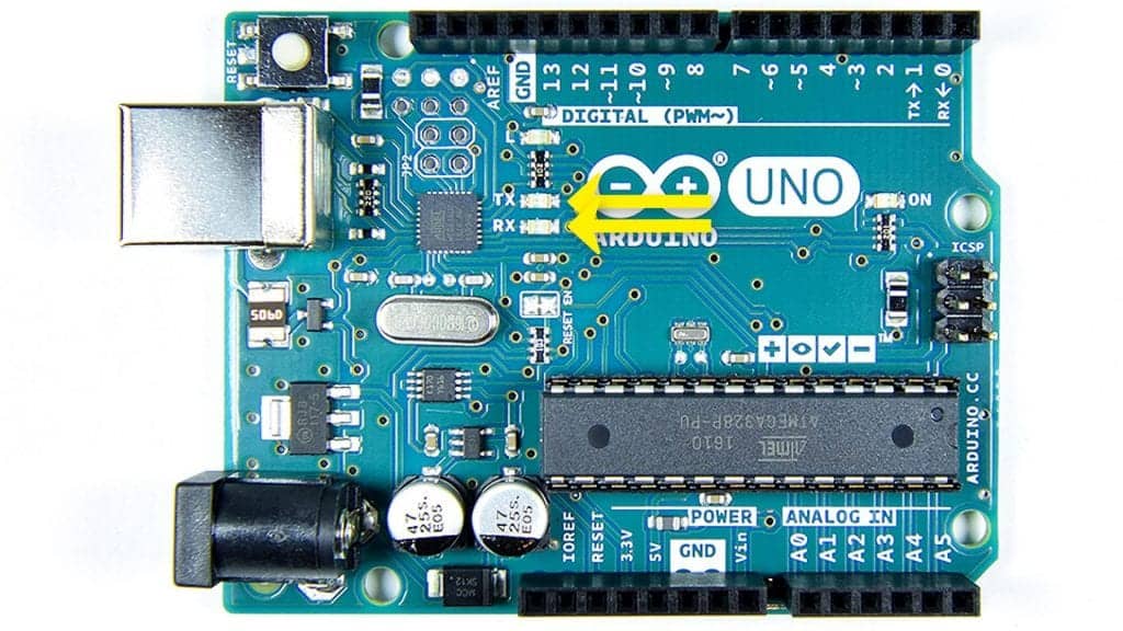
TX AND RX LIGHTS
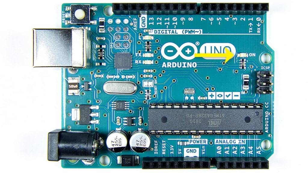
LED POWER


0 Comments